Technical
issues
Leakage around seal for pulley in one piece
Depending on the type of pulley of the
alternator, there are two versions for the seal between the
turbine part and the alternator compartment:
- Pulley consists of two halves: Then a
throw-off ring can be fitted in between the halves. The
narrow clearances between the separation sheet, this
throw-off ring and the "first sheet", act as a
labyrinth seal. This type was used for the 2 prototypes I
build and, once everything was well aligned and parts
didn't touch one another, it worked fine.
- Pulley in one piece: Then an inner ring
and a distance ring can be fitted in between the
alternator fan and the pulley. Now the narrow clearances
between the inner ring, the separation sheet and the
pulley side should act as labyrinth seal. I used this
type for two more chargers that I have build.
When I demonstrated a charger with a pulley in
one piece, I noticed that there was some leakage water at the
bottom of the alternator compartment. It did not pose a real
danger as it comes through the seal as a liquid and not as a fine
mist of water droplets that can be sucked into the alternator:
One could even drill a hole through the separation sheet at it s
lowest point to get rid of it. For that demonstration, I used a
pump that could only produce about 2 m head and maybe this
leakage only occurs at very low head. I had tested this charger
before with heads up to 12 m and then I did not notice any
leakage problem, but at those tests, water was splashing around
everywhere and I might have missed that some water did come
through the seal.
The most likely explanation for this leakage
problem I can come up with, is as follows: Probably the water can
come through because there is a jet of water leaking away between
the runner and the nozzle. This jet hits the separation sheet
just outside of the pulley and apparently, some water is forced
inwards through the narrow clearance between the pulley and this
sheet.
If the above explanation is correct, then a
solution would be to fit an anti-splashing ring
of 0.5 mm galvanised iron sheet, inner diameter = 6 mm, outer
diameter = 100 mm between the runner and the pulley (see bottom
left corner of the figure below). This ring should prevent the
water jet from splashing against the separation sheet at high
speed. I haven' t tested this solution yet, please let me know
whether it works.
 |
Seal
construction for a pulley in one piece, with-anti-splashing
ring
This
figure is a detail of new version of figure 4.12 of the building manual:
The seal and the way to fix the runner on the shaft (click on
it to get the complete figure).
In the printed
version of the Firefly building manual, this new anti-splashing
ring was not drawn. The drawing in the downloadable
version is correct.
Note:
When printed from within a browser, most likely the scale
is wrong. To get it printed on scale, copy this drawing
to your computer, open it with a graphical processing programme and
print it at 150 Dots Per Inch.
|
index page
Mechanical
regulators
During the mission to CLSU-ANEC and BSU-ANEC,
it revealed that the mechanical regulators they used, were rather
unreliable when fitted in a firefly switchboard. Probably, this
is because tiny sparks between the voltage regulator relay
contact points, makes those contacts stick together a little.
Apparently the field current of max. 3 A is enough to act as a
welding current, producing very tiny welds between those points.
Those tiny welds are strong enough to disturb the balance between
magnetic force generated by the relay coil, and the spring force.
And it is this balance on which the proper functioning of the
mechanical regulator is based. The effect is that the firefly
charger overcharges batteries: Once the battery becomes charged
and voltage surpasses 14.7 V, the regulator does not reduce field
current properly, but continues to provide full field current.
Consequenty the battery is charged further and battery voltage
rises to well over 15 V.
If this sparking effect happens in the firefly
charger, one would wonder why such mechanical regulators do
function in a car:
- With the car engine running, the voltage
regulator will vibrate. This is enough to make the
contacts come loose.
- The car engine drives the alternator up to
a much higher speed and with as much mechanical power as
it requires. Then the alternator can produce a much
higher charging current. This makes that battery voltage
with a fully charged battery rises well over 17 V, so the
voltage regulator coil will pull the contacts loose more
strongly. Once the contacts have been pulled loose once,
the voltage regulator will regulate towards a quite low
field current since the battery was already charged up to
such a high voltage. Then at this low field current, the
sparks are less strong, the contacts won't stick that
much and the regulator functions properly.
So with a more powerful alternator, the battery could be
overcharged badly, but for a very short time. This won't
damage the battery, while overcharging with a low
charging current for a long time, definitely shortens the
life span of a battery.
This problem can not be solved by readjusting
the regulator to a lower voltage. There is no way to predict how
much extra force is needed to pull loose sticking contacts and
quite likely, this will differ all the time. So trying to
readjust the regulator to a lower voltage could make that some
batteries are not charged fully while others would still be
overcharged.
Fitting the regulator in the alternator
compartment is not a good solution either. Of course, the charger
will produce some vibrations but when the runner built and fitted
neatly, it will be so well-balanced that the vibrations might not
be strong enough to make the contacts come loose. It might seem
simple to change the circuit diagramme of fig. 4.25 in such a way
that the regulator, the field current lamps and switches can be
fitted in the alternator compartment. But moving the points over
which the voltage regulator senses the voltage, does have an
effect on charging characteristics: If for instance the regulator
is connected at the alternator end of the alternator cable, the
resistance of this cable and the fuse will make that the
regulator senses a higher voltage, and consequently will reduce
charging current already at a lower battery voltage, see also par.
4.9.5.4. So if one wants to do this, the best way is to leave the
circuit as it is and fit extra wires from the switchboard to the
regulator.
Possible solutions are:
- Check whether the spark extinghuishing
diode is functioning properly, see fig. 4.31 of the
building manual for the circuit diagram. If there is a
resistor instead of the spark extinguishing diode, one
could replace it with a diode of at least 3 A capacity,
this will save some power also.
- Always install chargers in such a way that
they produce 100 W or more, see par 4.1 for minimum head
and flow required. Then battery voltage for a fully
charged battery will rise higher and there is a better
chance that the contacts will be pulled loose.
- Do not charge large capacity batteries in
parallel. Charging in parallel means that less capacity
is available for each battery, so battery voltage might
not rise high enough to pull contacts loose.
- As long as you are not sure whether a
mechanical regulator functions well: Check battery
voltage and charging current regularly.
- Even with a poorly functioning regulator,
the charger could be used if the operator estimates
carefully when a battery will be nearly charged, and then
checks say every hour.
If this doesn't help: Look for an electronic
regulator.
index page
Electronic switchboard
Compared to the standard switchboard, this
electronic version has the following advantages:
- It is more rugged. There are no moving
parts and as long as it is protected against water, it
will work accurately. Also with respect to electrical
overload situations, the circuit is well-protected.
- It is more user-frendly: There are just
two `on-off' switches, to connect the charger to either
one of the two batteries that can be charged at the same
time. A LED bar indicator shows state of charge of the
battery that is being charged and once this battery is
fully charged, this is also easily visible on the
indicator. The standard switchboard had an indicator with
a voltage and current range. For finding out whether a
battery was fully charged, both voltage and current had
to be read. Finding the actual state of charge of a
battery while it was being charged was even more
complicated , as one had to compare readings with graphs
about the charging process.
- The voltage regulator part of it can be
adjusted easily for a higher voltage than what is common
in cars (most car alternators are non-adjusted and then
special tricks are needed to set them to a higher voltage).
- With the voltage regulator part, there is
a field current adjustment. This has the same function as
the field current lamps of the standard switchboard, but
it doesn't have the energy loss of those lamps. Therefor
a charger with an electronic switchboard will be slightly
more efficient.
- It can be used for charging two batteries
in one go, see below with `discharge current LED'. Each
battery connection has its own indicator circuit.
But: It is more difficult to build than the
standard switchboard or the charge indicators. It should be
fitted in a well-sealed box or casted the electronic circuit
casted in epoxy resin to protect it against water. I think it is
a kind of gadget: Nice to have, it functions well, but it is not
essential. It could be an interesting option if large numbers of
firefly chargers were produced and series of this electronic
switchboard could be produced in one go. As far as I know, this
is not the case and I decided not to promote its use.
 The
electronic switchboard works as follows (see also drawing of
front plate and treshold voltages):
The
electronic switchboard works as follows (see also drawing of
front plate and treshold voltages):
- There is a voltage regulator part that has
an integrated field current control (the "speed
regulation" on the front plate).
- There are two indicator circuits, one for
each battery that can be charged. Like the charge
indicator that is used in the home systems, they indicate
battery state of charge in 10 steps.
For LED nr 10, there is a row of 3 LED's connected in
series. This makes the display more conspicuous when a
battery is fully charged.
- The indicator circuits sense whether a
battery is being charged or not:
In "initial mode", they use the same treshold
voltages as the charge indicator of the home system and
show whether this battery had been discharged too deep.
Then the display works in "dot" mode: Only 1
LED burns at any one time (or the top 3 that are
connected in series).
In "while charging" mode, they switch to a
different set of treshold voltages and show how far the
battery is charged already. Then the display works in
"bar" mode: All lower LED's burn as well.
For both modes, there is current compensation like in the
charge indicator for the home circuit.
There are switches for each battery connection and the
indicators already work in "initial mode" even
when the switch is "off". So a battery can be
checked even while another battery is being charged.
- There are discharge current warning LED's
that will light up when a battery with a "dead cell"
is charged in parallel with a good battery. Then dead
cell battery will draw a large charging current at a very
low charging voltage because one of its cells acts as a
short-circuit. This makes that the good battery might
help the charger to supply this large charging current
and the good battery might be discharged instead of being
charged, and you might end up with two worn-out batteries.
Treshold voltages for the
indicator part. The same series of LED's show battery state of
charge for both `initial mode' (when a battery that has just been
connected and is not being charged yet) and `while charging' mode.
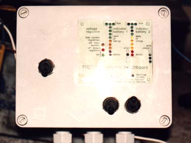 Electronic
switchboard made by mr Jaap Koppejan. It took him a couple of
days to build and it worked fine.
Electronic
switchboard made by mr Jaap Koppejan. It took him a couple of
days to build and it worked fine.
If you are interested to build one: Contact me
and I will send the building manual with circuit diagrammes, PCB
design, parts list etc.
index page
Adjustable nozzle
The second prototype I built in
Holland, had a adjustable nozzle that had a hinge in runner side
(see building manual for names of parts). This way, the end part
of runner side could rotate towards the bent side and a less
thick water jet would be produced. To avoid that too much water
leaked away at the edges of this moveable part, I mounted a piece
of rubber over the fixed part of runner side, the hinge and the
moveable part of the runner side. Later on, I realized that a
thick piece of rubber could serve as a hinge so a simpler
construction was possible. I haven't build this type of nozzle
yet.
 Some notes:
- There is a full-size
drawing. To get a paper copy on
scale 1:1, save the image on disk and print it at a
resolution of 150 dpi using a graphics processing programme.
- Because forces are now concentrated on the
fixed part of runner side, better use 2.5 mm material (instead
of 2 mm) for alternator side and free side. Then this
fixed part can be welded in stronger.
- With this adjustable nozzle, runner blades
are always hit by a water jet as wide as the nozzle, so
reducing the flow does not reduce peak forces on runner
blades. Therefor this type of nozzle can only be used
with heads up to 15.6 m.
- Tests with the second prototype showed
that turbine efficiency drops somewhat when flow is
reduced to less than half of full flow.
Generally, the standard nozzle will be the best
choice. Then blocking timbers can be used in case flow has to be
reduced. This is simpler to build, it does reduce peak forces on
blades and it can have a slightly higher efficiency at very low
flow. Such an adjustable nozzle could be useful for:
- A charger that is used for demonstrations:
It can be adjusted faster to the head at demonstration
sites.
- A charger at a site where available flow
is quite low and varying: Then every time the available
flow changes, the nozzle can be adjusted such that the
charger uses just less than the available flow. Having
the charger draw just a bit more flow than available is
no option: Air would be sucked into the penstock pipe and
net head as experienced by the turbine, would drop
sharply. Then this reduced head makes that flow drawn by
the turbine is reduced and matches available flow again.
Due to the low head, power output of the charger would be
very low.With a standard nozzle and blocking timbers, it
would be too much work to fit different blocking timbers
every time the available flow changes.
- For testing purposes.
index page