 |
| 4.7 | The frame | previous |
| index page |
The frame serves 3 functions:
The design of the frame is irrelevant as long as these demands are met. Use other material or a different shape for the frame if you like.
The frame design given in fig. 4.20 and fig. 4.21 is built from 25 mm angle bar. The total length needed is ca. 2.1 m. The basis is formed by the 200 x 200 mm square consisting of part 1 to 4. Angle bar itself is not strong against torsion and since the design includes no diagonal bars or a box construction, this square will be slightly floppy. Only when the alternator is fixed onto it, it becomes rigid. Therefor fixing the alternator to part 2 by means of part 15 is essential. Part 16 and part 8 could be left out, but then it will be more difficult to fix the alternator shaft at right angle to the separation sheet.
|
|
| Fig. 4.20: Parts of the frame. |
|
|
| Fig. 4.21: The frame assembled. |
| Box 4.13: Faster construction of the square.
In fig. 4.20, the square is made from 4 different parts (no 1 to 4) which are then welded together. An alternative is to make it from one piece of angle bar or 779 mm long with notches cut out where it will be bent to form the corners, see fig. 4.22. This way, welding will take less time but bending it properly to shape will be more difficult. So unexperienced people are recommended to make the square from 4 separate pieces.
|
For assembling the 4 sides of the square, clamp them onto a flat piece of steel or wood. Check whether the outer dimensions are 200 x 200 mm and whether the angles are straight, then make small welds just to fix them.
Welding the square properly at the inside of the corners is difficult, so better weld at the outside only. With the vertical welds, the two parts touch one another only at a corner and a groove is left that allows a strong weld to be made. At the flat side, both parts touch one another for the whole thickness and a weld will never become that strong. Also the weld has to be grinded flat afterwards so that the separation sheet will fit properly and this would make it even weaker. Therefor use the angle grinder to cut a groove where the seam is, fill that by electric arc welding and then grind or file the weld flat again. Also check whether the square as a whole is flat and, if not, bend it flat.
Drilling the holes in the square can best be done after it is welded together. The size and location of holes on the flat side correspond with those of the separation sheet in fig. 4.13, so clamp this on and mark where the holes should come. The proper location of the holes in upright sides can be derived from the holes at the flat side, or could be measured out. For an easy fixing of separation disk, side cover and shield, the frame is designed with holes with M5 thread in it. Then these holes must be drilled with 4.2 mm and an M5 thread tapped into them. However, using bolts and nuts would be just as good, in which case the holes should be 5 mm.
Now the alternator can be fixed. How it should be fixed exactly, depends on the exact shape of the connection lips on the alternator itself and on the way the seal was built, so don't just make part 14, 15 and 16 according to fig. 4.20. Measuring out exactly where the connection plates part 14, 15 and 16 should come, would be quite difficult. A faster and easier way is:
If the clearances within the seal are filled completely, the square should be fixed in the right position with respect tot the alternator. Better check this, especially whether the alternator shaft goes right through the middle of the separation disk and whether the shaft makes right angles with the separation disk.
There is another sneaky problem: The large welding current could damage the alternator bearings. The earth connection of the welding set will be somewhere on the square so as long as the arc is directed to the square, there is no problem. As soon as there is just a small weld between a connection plate and the square, again there is no problem because then there is an easier path for the welding current then to pass through the alternator bearings. But when starting to weld, things can go wrong. If bearings are damaged, no one will notice until they are worn out, maybe only after hundreds of operating hours.
This problem can be dealt with in several ways:
Clearly the first way is the fastest, but it is also the most dangerous one since contact surfaces might not be that good, parts might move a little when trying to start the welding rod etc. The second way is quite a lot better, but still there might be problems with rusty contact surfaces. Therefor the third way is recommended. For 0.5 mm, about ... layers of ordinary paper or ... layers of electrical tape will be needed. Of course, also plastic sheet could be used. Pay special attention to the clearance within the central hole in the separation sheet. This hole might have sharp edges and if the alternator is moved a little, the edges can cut through isolation material. If you are not sure, check with a tester whether the alternator is isolated from the square before starting to weld (for testing whether parts make contact within the seal, part 14 and 15 should of course not make contact with the square).
When this is all sorted out, weld part 14 and 15 to the square with some small welds at places where they could be grinded away easily when necessary. Then weld part 8 and 16 onto this, again with small welds. Now remove the filling material from the clearances in the seal, assemble it again and check whether the runner can rotate freely. If it doesn't, decide what to do about it:
The last option is the most drastic one. Before doing it, find out exactly what made things go this bad. Maybe the runner or rotating disk themselves were badly aligned on the shaft and this caused that the square was fixed badly aligned as well. Also find out in which direction these parts should be moved in order to have things fixed straight.
The second option is not ideal either. When holes are enlarged to make things fit, it is quite a job find back the proper position for the alternator after every time it has been removed.
When there is no need to start all over again, remove the alternator and separation sheet and weld these parts on properly.
Weld part 5 and 6 on the square. Like with the square itself, make small welds on the inside corners to fix them, then grind grooves at the seam from the outside and fill these by welding. Then cut out the rough shape of part 17 and weld it on the square, using the same method.
For fitting the nozzle properly, first fit the alternator, separation sheet and runner again. Take special care that the runner is fitted well-aligned. Check whether the nozzle fits properly onto the runner. Of course the protruding bit of the bent side has to be filed off, but check the alternator side and free side as well and file bit by bit until it has a good fit. Of course this makes no sense if the runner itself was not filed round properly. In that case, find another object that has a cylindrical shape with a diameter of 75 mm or check the nozzle against the drawings.
Hold the nozzle against the runner and roughly draw on part 17 how much material must be removed. Carefully cut, grind or file away this material, checking regularly where some more must be removed to make the nozzle fit well-aligned to the runner, leaving an equal margin at both the alternator and free end of the runner. It seems logic to have a right angle between the pipe of the nozzle and the side of the square, but then the nozzle partially covers one of the screws that fixes the separation disk. So position the nozzle in such a way that this screw can just be fixed and removed easily. Then check whether part 7 fits in between part 5 and 6.
To fix the nozzle, put the frame with the alternator on its side. Now have the nozzle rest with one end on the runner and with the other end on some boards of wood that are made so high, that it fits well into part 17. To make sure that the welding current will not pass through the bearings, put a few layers of paper between runner and nozzle. This will also make that there is a minimal clearance between runner and nozzle. Check whether the nozzle is properly positioned and put some heavy weights on the nozzle so that it will not move while starting to weld.
First weld the nozzle to part 17 with a small weld. Check whether it is still aligned properly, quite likely it is not due to shrinkage of the weld. Bend it to shape, use ropes, weights or clamps to fix it into the right position or cut in one end of the weld with a chisel so that it will bend wider there. When things look too bad, grind away the weld and start all over. Then make a second weld to part 17. If there is a gap at that place, put a piece of steel in between that will prevent shrinkage as much as possible. First weld part 7 to 5 and 6 and then, in the same careful way, to the nozzle. Remove the paper, check whether the runner did not get stuck completely and check whether the clearance between runner and nozzle has not become too large (0.5 mm is still acceptable). If it all looks pretty good, finish welding in the nozzle. Only weld at the outside so that the welds could be grinded away later. There is no need to make large welds all around and in fact trying to make a thick weld could mean blowing a hole in the pipe if it was only 2 mm thick.
Probably the runner does not rotate freely yet. Just forcing it to rotate and let the material wear out means making grooves onto the edges of the blades and that is no good, better file or grind off material from the nozzle. If the runner can still rotate when driven with some force, hold sandpaper against it (with grains on the outside) and rotate the runner until the sandpaper ends up between the nozzle and runner. Use medium size sandpaper since coarse sandpaper would be too thick. Rotate the runner to and fro until so much of the nozzle is grinded away that the two don't touch any more. Likely the grains of the sandpaper rub off soon and it tears easily, but don't give in too soon since the alternative also involves quite some work.
If the runner cannot rotate or if too much has to be grinded away, the sandpaper method is no good. Then the runner must be taken off so that the nozzle can be filed to shape. First mark carefully where material must be filed off and how much, remove the runner, file off the nozzle as planned and fit the runner to try again. Especially fitting the runner and aligning it properly every time to try out, makes this method quite laborious. Finally, the holes for fixing the adjustable leg 13 must be drilled in part 17 and 7. Position the holes in such a way that: The adjustable leg will stay free of the nozzle pipe. Both holes are aligned vertically. The distance between them is 80 mm. There is space for a bolt head. The holes do not end up too close to the edge of the material. If no such positions can be found, choose a smaller or larger distance between them and drill the holes in part 13 accordingly.
If a nozzle with flange was fitted, the flange will just be in the way for drilling the hole in part 17. So either drill from a small angle (take special care that the drill goes in where you want it, since it will tend to `walk away') or the adjustable leg should be moved a bit further away from the pipe of the nozzle.
Making the legs is quite straight-forward. Only cutting the top ends of rear legs 9 and 10 is a bit weird since the cut should have a 45° angle at both sides of the angle bar. To allow for the side cover to be fitted later, have washers between adjustable leg 13 and the square. Bending the bottom lips of the legs can best be done when they are assembled onto the frame.
Now the frame should look like fig. 4.23, exept for the fact that on this picture the left and right rear leg were interchanged so that the lips at the bottom ended up on the wrong sides. Stupid, but maybe the fact that I make such mistakes will be a comfort to readers who felt stupid after making mistakes...
A bit of paint on the frame, nozzle and runner will make the charger look much better, but there is no real need for this. More important is to apply grease on all screw threads and on the alternator shaft before things are finally assembled.
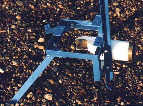 |
Fig. 4.23: The frame with the nozzle welded on. |
| 4.8 | The covers and shield |
The covers can be made from flat galvanised iron sheet of any available thickness (the same material as for corrugated iron sheet, but then flat), see fig. 4.24. At the rear side of the side cover, the cable to the alternator passes through. This cable should not be cut by the sharp edge of the G.I. sheet, so fit a special rubber ring for this, bend the edges round, fit a piece of hose or protect the cable by a thick layer of electrical tape.
|
|
| Fig. 4.24: Covers and shield. |
There is a gap between the top cover and the sides for ventilation. The edges of the top cover are bent downwards so that even with strong winds, no rain can enter the alternator compartment through this gap. The top cover is fixed on supports at each corner. These must have a thread tapped into them because there is no way to hold the nuts in place when fixing the top cover. If tapping M5 thread is a problem, these supports from thin galvanised iron sheet and use special `parker' screws for steel sheet to fix the top cover.
For safety, there should be a protective shield around the turbine part. The danger area is the point where the runner approaches the nozzle. If something touches the runner there, it might be dragged into the narrow gap between runner and nozzle. Then quite likely either this foreign object or the nozzle and runner get damaged. Anything touching the runner at another point around its circumference is rather harmless. Seen in the direction of movement of the blades, their edges are directed backwards so the blades will not cut into such an object, but just push it outwards.
The most likely cause of trouble are curious children. They might enjoy the feeling of the water splashing around and then try to touch the runner itself. Also they might stick a piece of wood towards the runner. Even if the shield is not so good that children cannot possibly get their fingers near the runner, it might still be effective enough as long as it makes clear that this is a forbidden danger zone and they should keep those fingers out.
The shield can be made from galvanised metal mesh (with wires that are welded where they touch). Choose a mesh that is made from rather thick iron wire (say 2 mm) so that the wires themselves are thick enough to be made into the eyes that are needed to fix the shield. It doesn't matter if such a mesh is too coarse to keep out for instance childrens fingers. Then just fix an extra layer of mesh at the bottom of the shield so that in effect, the mesh has become twice as dense. Also a shield that can not keep out all fingers, sticks etc, still makes pretty clear that one should not mess around with the turbine.
For a shield, 500 x 500 mm mesh is needed. The middle section will become the bottom part of the shield and to get it to shape, pieces have to be cut out at the corners so that the 4 sides can be bent upwards. When cutting out these corners, leave enough length on the wires so that they will overlap and can be soldered together using ordinary soft solder and a heavy soldering iron. If soldering alone might be too weak, tie wires together using thin iron wire before soldering.
Alternatively, the shield can be made completely from galvanised iron wire, but this is a lot of work. Then an old steel shopping basket forms better material to start with.
Quite understandably, the shield won't be a priority for someone building a charger. For testing, it is not necessary yet because there will be somebody to watch out. But when it is not made together with the rest of the charger, quite likely it won't be made at all, local people get used to it and see no danger in an unprotected turbine, subsequent chargers will have no shields. And then maybe once a child loses its finger...