| 4 | The charger | previous |
| 4.1 | Standard charger design | index page |
In this chapter, the standard charger design will be discussed. This design is a `general purpose' design that will do for a wide variety of situations. To keep it simple, it is meant for charging one battery at a time. For more extreme situations or if a higher power output is needed (so that it can charge a number of batteries in one go), the design can be adapted, see annex B.
From a technical point of view, it would be best to make chargers `custom-built'. Then charger design can be adapted to the head at the site, the alternator type that is built into it and to the power output users want from it. However, sticking to one standard design has advantages:
In designing the turbine for the charger, a compromise must be sought between two conflicting demands:
The head at which the charger will operate, also plays a role in this:
Below a certain head, no such compromise can be found any more. Then one could build a charger with a V-belt transmission so that the runner can be built big enough to accomodate the flow while the transmission makes that the speed of the alternator will be high enough. This is not an attractive option because the V-belt transmission will make the charger more expensive and more difficult to build.
|
Fig. 4.1: The standard charger: Not a big thing. The shield around the runner is not fitted yet. |
See annex B.2 for a further explanation of the principles behind designing a firefly charger. Here only the standard charger design and its characteristics will be discussed.
Important dimensions for the standard charger are:
| Runner diameter: | 75 mm |
| Runner width: | 55 mm |
| Blade angle at outer radius: | 36 ° |
| Number of blades: | 27 |
| Thickness of blades: | 1.25 mm* |
| Nozzle width: | 51 mm |
| Nozzle admission angle: | 75 ° |
| *) If 1.25 mm thick steel plate is not available, 1.00 mm steel plate can also be used but then the maximum allowable head will be lower, see fig. 4.3. | |
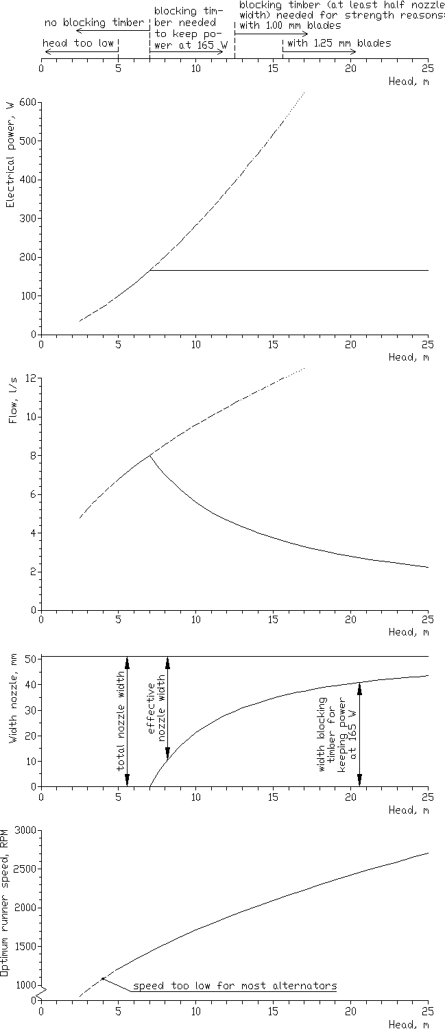
From these figures, the characteristics of the standard design charger can be calculated (see annex B.2.5 for how to make those calculations). The results are given in fig. 4.3 and some of them are summarized in table 4.1.
The table shows that the standard charger needs a head of at least 5 m to generate 100 W or more. Just 100 W electrical power is a bit low, but still high enough to charge even quite large batteries within daytime only. Also optimum runner speed is low but still well above 1000 RPM, which is the absolute minimum speed for most alternators. For 3 m head, the standard design will not do, since both electrical power and runner speed are too low, see annex B.3 for a design adapted to low head.
The table also shows that when head increases, electrical power increases rapidly. In fact, power output becomes too high for charging just one battery at a time once the head is higher than 7 m. At 7 m head, electrical power is 165 W, which means that the charging current will be 11.8 A (11.8 A times 14 V makes 165 W). This is already quite a high charging current for small car batteries, see annex C `more about batteries'.
In order to keep the power output at around 165 W even when head increases above 7 m, the flow through the charger must be reduced. This could be done by fitting a less wide nozzle, but one could also use one size nozzle for all conditions, and when necessary: Fit a piece of timber inside the nozzle that will partially block it: A blocking timber. Then only the blocking timber has to be made for the head of a specific site, with its width adapted to the head of that site. Or one could bring a set of blocking timbers with different widths and choose the one that is closest to the desired width.
| No blocking timber: | With blocking timber: | |||||
| head, m |
optimum speed, RPM |
flow, l/s |
power, W |
width, mm |
flow, l/s |
power, W |
| (3 | 940 | 5.3 | 46)* | |||
| (4 | 1080 | 6.1 | 71)* | |||
| 5 | 1210 | 6.8 | 100 | |||
| 6 | 1330 | 7.4 | 131 | |||
| 7 | 1430 | 8.0 | 165 | |||
| 8 | 1530 | 8.6 | 202 | 9 | 7.0 | 165 |
| 10 | 1710 | 9.6 | 282 | 21 | 5.6 | 165 |
| 12 | 1880 | 10.5 | 371 | 28 | 4.7 | 165 |
| 15 | 2100 | 11.8 | 518 | 35 | 3.7 | 165 |
| 17 | 2230 | (12.5 | 625)* | 38 | 3.3 | 165 |
| 20 | 2420 | (13.6 | 797)* | 40 | 2.8 | 165 |
| 25 | 2710 | (15.2 | 1115)* | 43 | 2.2 | 165 |
*): Values between brackets mean that the
charger can not be used under these conditions:
|
||||||
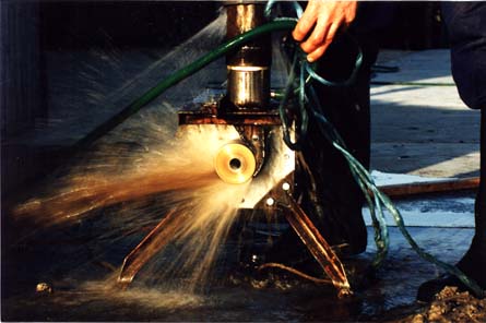 |
Fig. 4.2: The charger seen from below. The amount of water coming through it is quite impressive. |
The table shows that now flow decreases as the head increases further and the blocking timber is made wider and wider. This means that at a high head, the charger could do with a relatively small water source.
Another important characteristic of the runner design is the maximum allowable head. This is the maximum head at which the charger can operate without risking that eventually blades will break out: Blade Maximum thickness: allowable head: 1.25 mm 15.6 m 1.00 mm 12.5 m In fact the quality of the soldering of the blades is more important than blade thickness itself, see box 4.10. So if soldering is questionable, it is adviseable to stay well below these limits.
The above values for maximum allowable head are valid in case no blocking timber is installed. With a blocking timber that blocks at least half the nozzle, forces on the blades are reduced so much that a much higher head is acceptable. When head is 11 m or above, the blocking timber should be made half the nozzle width or wider. This means that with the correct blocking timber installed, the strengh of the blades poses virtually no limit to the head, even with the 1 mm blades.
However, the seal around the shaft does put a limit to the maximum head. When head is very high, the speed becomes so high that the alternator fan could suck air with water droplets through the seal. It is hard to predict until what head the seal will work satisfactorily since it depends on the shape of the pulley and fan of the alternator. For the time being, it seems safe to assume that this charger design can be used up to a head of 25 m when the correct blocking timber is installed and the seal is made carefully according to the design. The calculation of electrical power output given in the table and fig. 4.3 is based on an estimated overall efficiency of higher and consequently power 0.30. This is a safe estimate, so usually efficiency will be a bit output will be higher than expectedinefficient alternator, efficiencies of up . For a charger fitted with a rather to achieveable for chargers fitted with high 0.38 have been recorded and an efficiency of up to 0.45 seems capacity, efficient alternators running under favourable conditionsseems a pleasant surprise if the charger . It turns out to produce more power than expected, but it could also cause problems: If the turbine part is built neatly, efficiency might come close to efficient, high capacity alternator is used, 0.40 and if also an highly overall efficiency could reach output will be 1.5 times higher than given 0.45, meaning that electrical power in current would be too high for just one fig. 4.3 and the table above. Then fuses might blow and charging battery. Of course the solution is simple: Fit a larger blocking timber.
|
|
| Fig. 4.3: Characteristics of standard charger. |
| 4.2 | The alternator |
To keep costs low, the charger is designed for fitting a second-hand car alternator. Many different alternator types exists and it is no use to recommend one type: It might not be available, while other types that are just as good, are. Alternator types could differ with respect to:
With respect to their suitability for use in a firefly charger, the following things are relevant:
For checking whether alternators have such a circuit and for modifying the circuit of alternators with a different electrical circuit inside, see annex A.
Generally speaking, older alternator types of Japanese brands (Hitachi, Nippon-Denson and Mitsubishi) have the right electrical circuit. Also older types of some europese brands (Bosch, Ducellier, Paris-rhone and Fiat) have an electrical circuit that can be used without problems. However, not all alternator types of these brands will have this circuit and to find out, one could look at the codes that identify the external connections:
Of course one could also open up the alternator and see how things are connected inside, or make some electrical measurements on the outside connections that reveal how things are connected inside, see annex A.
When buying an alternator, mind the following points: Choose one of the brands named above and with the right codes for connections. If no such alternator is available:
The physical dimensions of the alternator are not so important because the frame can be adapted in such a way that it will fit properly. Only the largest alternator types might give a problem if they do not fit inside the 200 x 200 mm cover.
If the supplier has a test bank for alternators, ask whether he could demonstrate the alternator you are about to buy. Relevant in this are:
If the alternator performs worse than expected, either the type is unsuitable or the alternator is defective inside, probably conductor rings and brushes are in bad shape, stator coils are burnt or diodes have blown out.
Make notes on speeds and charging currents, and also about whether it was connected to a mechanical or an electronical voltage regulator during testing. Try to figure out whether alternator speed is measured accurately. Either a measuring device must be connected directly to the alternator shaft or the operator should measure the transmission ratio of the V-belt transmission between the driving shaft and the alternator shaft, and adjust the speed indicator accordingly.
It is best to buy the (external) voltage regulator together with the alternator. Important characteristics are:
| Box 4.1: Condition of the alternator.
When buying second hand goods, there is always a risc of buying rubbish. It would be best to make some fast checks on a second hand alternator before buying it, but one needs experience for this, and a thorough understanding of how an alternator works. So probably it is best to have the seller guarantee that this alternator works, that the voltage regulator is compatible with it, and make clear to him that if you would find out later that something was wrong, you will claim your money back. If you don't trust the supplier and can not afford the extra trouble a malfunctioning alternator might cause, consider buying a new one or one that has been reconditioned by an official dealer. Some fast checks that can be done when buying an alternator:
Of course a bad alternator can be repaired and reconditioned but this means extra work, see par. 4.11.2. |
When looking at them from the pulley side, almost all alternators are designed to run to the right (in the direction of the hands of a clock). This must be taken into account in building the turbine parts so that in the charger, the alternator will run in its proper direction. All drawings are correct for alternators running to the right.
Often the proper direction of rotation can be seen from the fan: When running in the right direction, the blades will push the air outwards and the fan will work efficiently. Sometimes there is also an arrow on the fan indicating the proper direction of rotation. Sometimes the brushes are not directed straight towards the hart line of the shaft and then these make that it is meant for one direction only, see box 4.2.
| Box 4.2: Orientation of brushes and direction of rotation.
When the brushes are not directed straight to the hart line of the shaft but at a small angle, the direction of rotation influences the friction forces the brushes will experience when they move inwards or outwards of the brushholder. These friction forces will be lowest when brushes are directed against the direction of rotation of the shaft. Then the friction force of a brush on its conductor ring will be directed against the spring that pushes the brush outwards. Consequently forces against the sides of the brushholder are minimal, the brush can move freely and it can easily follow an irregularity of the conductor ring if that happens to be slightly excentric. One would expect that if the brushes are not directed straight to the hart line of the shaft, they would be directed a bit against the direction of rotation of the shaft. This was common practice for instance in the older Decent Current generators that were used in cars before alternators took their place. But with car alternators, it turns out not to be the case: Some Japanese alternators have brushes directed with the direction of rotation. This means that brushes will experience extra friction forces when they are pushed inwards or move outwards of their brushholder. Consequently they can not follow the conductor ring that easily if this part is slightly excentric. When running at the relatively low speed that is common in a firefly charger, such an alternator might perform better when it runs in the wrong direction: Then brushes follow irregularities better, resistance over brushes and conductor rings is lower, field current is higher and the alternator has a lower starting speed and can produce a higher charging current at working speed. It is unclear to me why alternators are built this way. Maybe this construction makes that the conductor ring will wear out in such a way that it remains perfectly centered. If one comes across an alternator that performs better when running in the wrong direction, one might consider building the charger in such a way that it does run in this `wrong' direction, so: To the left. Then the runner, nozzle and frame have to be made as mirror images of the drawings in the book. The fact that then the fan runs in the wrong direction is not that important since the alternator is used way below its rated capacity and therefor does not need much cooling. I think there is little sense in this. There must be a good reason why the brushes are placed as they are. And if the alternator does not perform well when running in the right direction, it is better to solve the real problem: Have the conductor rings reconditioned on a lathe and maybe fit new bearings without play. |