 |
| 4.3 | The runner | previous |
| 4.3.1 | Making the blades | index page |
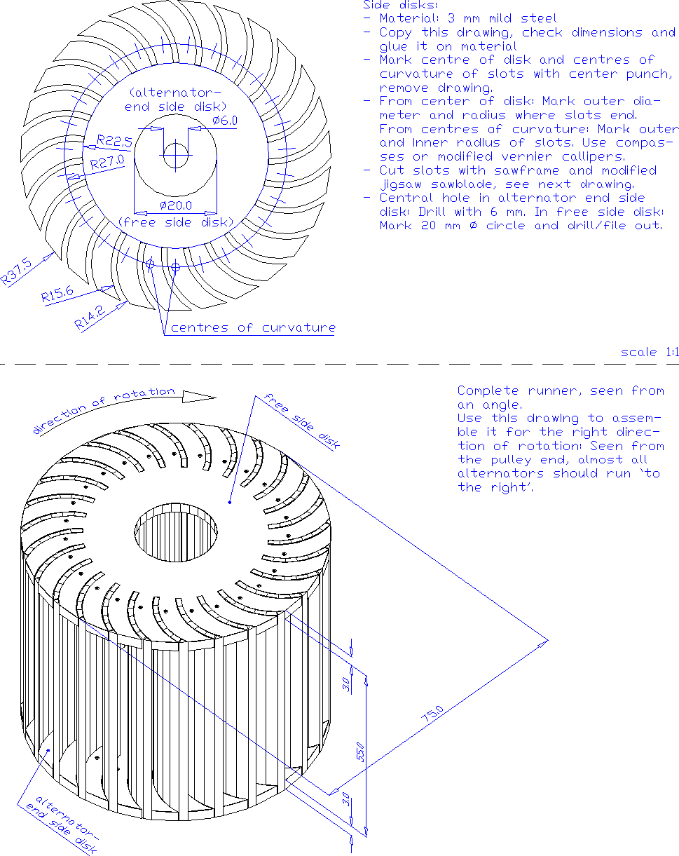
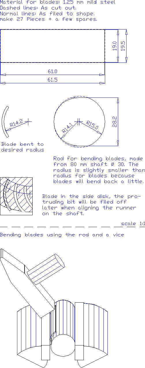
See fig. 4.4 for an illustration on how to make the blades.
Preferably, the blades should be made from 1.25 mm mild steel. If this is not available, 1.00 mm will also do but then the maximum allowable head will be slightly lower, see par. 4.1.
Since the blades will be soldered with brass later on, all paint or zinc (if it was galvanised) or `roller skin' (the black layer that is present on new, warm-rolled steel) should be removed. Once the blades are cut and bent to shape, it is much more work to clean them, so better do it on the piece of steel sheet the blades will be cut from later. Use a steel scraper and coarse sand paper for the last finish. Sometimes `blank' steel sheet is sold, with a smooth silvery color. In that case there is no roller skin. Real roller skin is almost black with a slight blueish hue.
Eventually, the blades are bent from rectangular pieces of 61 x 19.0 mm. The corners should be straight since that makes it easier to make a straight runner later on. The blades can be cut in several ways:
It is important that all pieces have the same size and shape as this makes it easier to built them into a straight runner later on. Also the edges should be smooth since irregularities could act as the start of a crack later on. Therefor cut slightly bigger pieces of say 61.5 x 19.5 mm and file them to shape. About 15 can be clamped carefully aligned in the vice and filed in one go. When using a cold chisel to cut the pieces, the initial sizes should be even a bit bigger, say 62 x 20 mm. The runner needs 27 blades, but better make some more so that a few off-types can be discarded.
| Box 4.3: Blades with rounded inner sides.
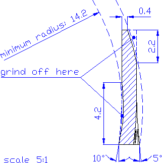
For making a runner with a high efficiency, it is recommendable to have the inward side of the blades rounded. Then the water will flow more smoothly around them after crossing the empty inner space inside the runner. Rounding off blades could best be done before bending them. If blades are rounded at the inside, they could also stick about 0.5 mm more inwards toward the center of the runner and therefor become a bit stronger. Still blades of 19 mm wide can be used, but now less will be filed off at the outer edge when aligning the runner. Remember to cut the slots in the side disks 0.5 mm deeper when using rounded blades. |
|
Fig. 4.4: Making the blades. |
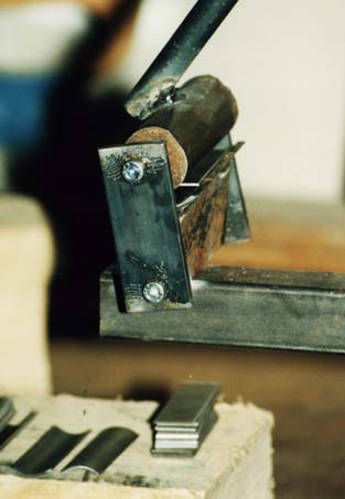 |
Fig. 4.5: Bending blades with a makeshift press. |
For bending them, you need a piece of shaft with a diameter of 28.2 mm (28.0 to 28.5 mm will do) and slightly longer than the blades themselves, say 6580 mm. In a steel workshop, such a rod can be made easily on a lathe. Then one only has to file a flat side on it so that it holds better in the vice.
If you have to make one yourself, get a piece of 30 mm shaft or a long 30 mm diameter bolt to start with. File 2 flat sides on it until the thickness between the sides is just 28.2 mm. Then start rounding off one of the curved ends until there is a smooth curve with a constant radius from one end to the other.
Put the rod and a blade together in the vice (see fig. 4.4). To prevent that the blade will bend in a screw-like shape, make sure that the rod is well-aligned with the blade. Then slowly hammer the blade around the rod. Turn the blade upside down to hammer the other end into shape. It will look as if you can't get the blades into shape because they will always bend back a little. This is no problem since the radius of the rod was made slightly smaller than the desired radius of the blades to compensate for this effect. If you would hammer too long on the edges, the blades won't be straight lengthwise anymore.
| Box 4.4: Bending
blades in series.
Blades could also be bent to shape using a press as shown in fig. 4.5. It consists of a 28.2 mm diameter rod and an outer mould that forms the correct outer radius, made from a section of a suitable size pipe. When operating the handle connected to the rod, it will press downwards into the outer mould and bend most of the blade. Repeating this after the blade has been turned around will do the rest. |
| 4.3.2 | Making the side disks |
The side disks are very important parts. If they are built correctly and accurately, it is relatively easy to build a strong and straight runner that will work efficiently. Likewise, if the shape of the side disks is lousy, it will be much more difficult to build a proper runner.
The procedure described in detail below is meant for producing a few side disks by cutting them by hand. To cut the strongly curved slots for the blades, it makes use of jigsaw sawblades (the ones designed for use in a jigsaw machine) that are fixed in a homemade sawframe. Advantages are that little preparation work is needed and one can see what one is doing, making it possible to cut them reasonably accurately right from the start.
For making side disks in series, cutting by hand would take too long and it becomes economic to cut them using a jigsaw machine, see box 4.9.
| Box 4.5: Building or buying side disks.
Considering the time it takes to cut side disks by hand, it could be advantageous to buy a few side disks rather than making them oneself. Since soldering in the blades is also a critical step, it makes sense to buy a complete runner and maybe even the nozzle. These items are light enough to send by air mail and not too expensive. Prices excluding postage are: 2 side disks: ƒ 80, complete runner: ƒ 200, nozzle: ƒ 130. See also par. 1.2. |
| Box 4.6: Using side disks without slots.
The 2 prototype firefly chargers had side disks without slots. The blades were clamped in between the 2 side disks rather than sticking through them. This construction saves the trouble of cutting the slots in the side disks, but has other disadvantages:
Therefor this method is only adviseable for people who have experience with brass soldering and have no time to make them with slots. Then blades must be made 6 mm shorter to arrive at the same runner width and only 20 blades can be fitted. Take into account that the maximum allowable head will be only 11.6 m with 1.25 mm blades, and 9.3 m with 1.00 mm blades. |
The side disk drawn in fig. 4.6 shows the size and placing of blades. The firefly runner deviates from crossflow design theory, see box 4.7.
|
|
| Fig. 4.6: Making side disks. |
The side disk is drawn on scale 1 : 1 and indeed, it is quite small. This leads to two problems:
Answering the first problem comes down to not trying to measure out all dimensions oneself, but merely copying it from paper onto steel.
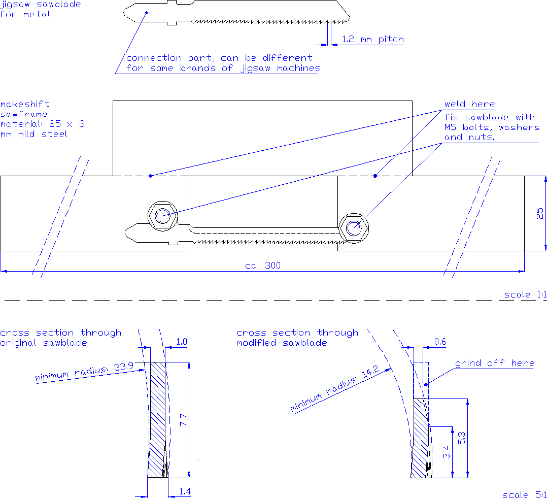
To answer the second problem: Jigsaw sawblades have to be grinded off until they can make such sharp curves. The easiest way is by grinding off at the rear end only, see fig. 4.7, and this is the best way if one wants to use sawblades in a saw frame. It could best be done using a bench grinder. Standard sawblades for metal could be used, but they have a rather short usefull length of only 50 mm. It is worthwhile to look for extra long sawblades that are more efficient for sawing by hand.
Without special measures, such a grinded off sawblade can not be used in a jigsaw machine anymore because the rear end doesn't touch the support wheel any more. In a jigsaw machine with an orbital mechanism (meaning that the sawblade is pushed a bit forwards on the upward stroke), the vertical, up and down-going shaft might have so much play that the sawblade is still supported by the support wheel. But then there is still another problem: The rear end of the sawblade must have the right, slightly conical shape, which is difficult to achieve once one has been grinding off material at that end. So if one would like to use a jigsaw machine, it is better to modify sawblades according to fig. 4.10. See also box 4.9.
The shape of the sawframe itself is not so important, as long as it holds the sawblade well, see fig. 4.7. When using extra long sawblades, of course the sawframe should be adapted to this.
|
|
| Fig. 4.7: Using modified jigsaw sawblades for cutting slots in side disks. |
Addition to internet version: Hacksaw sawblades can be used also.
In charger building workshops in the Philippines, people used hacksaw sawblades of
which about half of the height of the blade was grinded away and probably even more at the
side where it touches the outer edge of the slot. With such sawblades fitted in a normal
hacksaw, they could cut the slots quite fast. However, the side disks I have seen, had slots
with radiuses quite a bit larger than the design value of 14.2 mm and consequently, blades
will be less strong. Also the width at the teeth is only 1.0 mm instead of 1.4 mm for
jigsaw sawblades. One could try to widen the slot by cutting away material from one of the
sides, but this means extra work and a less smooth result. Normally, only 1.0 mm thick
blades will fit in (instead of 1.25 mm) and this makes the blades even weaker. If you are
interested, see the picture "Joel Cubit cutting a side disk" in:
http://www.microhydropower.net/mhp_group/portegijs/firefly_exp/ANEX_s.html
Some practical advice on cutting slots with a makeshift sawframe:
Then the 6 mm hole in the center of the alternator side disk can be drilled in (try to get it as well-centered as possible). The 20 mm hole in het free side disk can be made by drilling first with the largest drill bit available and then filing out the rest (mark the 20 mm diameter circle before drilling away the centre point that represents its centre). Or it can be made by drilling a line of small holes along the edge, cutting out the center bit and then filing it to shape.
| Box 4.7: Firefly runner and nozzle design.
Crossflow design theory (see e.g. ARTER & MEIER, 1990) gives key relations between parameters that govern runner geometry. In the table below, a commonly used set of parameters is presented. The firefly runner design deviates from these:
The most important difference of the firefly runner with crossflow theory is its large radius of curvature of the blade. This makes that the firefly blade is stronger. But the main reason for it is a practical one: Cutting slots with an even smaller radius of curvature would become very difficult. Having such a large radius of blades inevitably means that inner radius ends up quite small. According to crossflow theory, this is incompatible with the large blade angle at the outer circumference since it will create back pressure: At the inner radius, the space between two blades becomes too narrow so the flow is partially blocked there. So a pressure is needed to push the water through this narrow area and then this pressure can also be found at the outer radius. It is this pressure that makes some water leak through the gap between runner and nozzle. I think this is not enough reason to do away with the firefly runner design. In practice, a crossflow runner designed according to the theory will also have back pressure because:
Tests showed that a firefly with the nozzle designed for an entrance angle of 20°, consumed a flow that was ca. 12 % lower than calculated. This means that back pressure in the firefly must have been quite large. Therefor nozzle design has been adapted so that it will feed the same amount of water into the runner, but spread it over a wider admission angle. So the new nozzle design has an admission angle of 75° (was 60°) and feeds water at an entrance angle of 16° (was 20°). Now the entrance angle as produced by the nozzle (= 16°) does not fit any more with the entrance angle the runner was designed for (= 20°). In fact, the difference is a bit smaller: Theory prescribes the form of the `skeleton line' of the blade (= line right in the middle between its inward and outward surface), while in fact it is the inward surface that deflects the water. I don't think this is a problem, I expect it will make that blades will `scoop up' the water from the nozzle more easily. Theory predicts that turbine efficiency would rise by 4.6 % when runner design would also be adapted to an entrance angle of 16°. But if one takes that theory seriously, one should do away with the large blades of the firefly and build the runner completely as prescribed by the theory. No efficiency figures are available for the turbine part alone, but an overall efficiency of up to 0.388 for the complete charger suggests that not much can be wrong with turbine efficiency (according to HARVEY, 1993, alternator efficiency should be around 0.60 so turbine efficiency must be 0.65). However, this issue deserves attention and maybe in a future version, runner design will be adapted as well. Reducing the entrance angle to 16° without changing the inner radius would make the blades even stronger. For people who want to build a runner this way: Have the centers of curvature at a radius of 26.4 mm (instead of 27.0 mm) and make the radius of curvature of blades 13.8 mm (instead of 14.2 mm). |
||||||||||||||||||||
| Box 4.8: Modifying a vernier calliper for marking circles on steel.
The points at the jaws for `inside' measurements of a vernier calliper can be used already as compasses for steel: Have one jaw in a center point and scratch with the other over the material. The material of a proper vernier calliper is hard enough to scratch into steel without wearing out too fast. Problem is that one doesn't know exactly what radius the circle will get since the first jaw doesn't align well with the center point. To solve this, the vernier calliper can be modified a little: Adjust the calliper to 1.0 mm exactly and fix it well. Now the `inside' jaws largely overlap but the points themselves are 1.0 mm apart. Grind off the overlapping inside jaws until together they form one point shaped more or less like the point of a center punch (say: with 90° top angle). Now the vernier calliper can be used as compasses and the radius can be set using its scale. The one thing one has to remember, and is likely to forget, is that one should add 1.0 mm to the desired radius because, when adjusted to 1 mm, the points overlap again and the radius is 0. Because of its scale, such a modified vernier calliper is easier to use and more accurate than real compasses for steel. However, the points of its inside jaws are modified and therefor `inside' measurements of objects with only a small rim, will be more difficult.
|
| Box 4.9: Making side disks in series.
For making series of side disks, a sturdy jigsaw machine can be used with an especially made foot plate that works as a circle guide. The pin of the circle guide falls into the holes of a mould that is clamped onto the side disk to be cut. To make it possible to cut at some speed without overheating sawblades, the sawblade should be cooled using drilling fluid. Therefor a container with drilling fluid is needed, with a support for the side disk being cut in the middle. With every stroke, the sawblade dips into the drilling fluid and is cooled in that way, see fig. 4.9. Advantages of this method are that up to 2 side disks per hour can be made, once everything works well. Accuracy of the side disks can be very good and if there are errors, quite likely all slots have the same error. Disadvantages are the investment costs of the jigsaw machine, it will take days of work before the first side disk can be cut, probably the first ones aren't that good and it takes quite some metal working skills to get everything to work properly. For use in a jigsaw machine, it is better to modify the sawblade according to fig. 4.10. To make that the support wheel will function well, the rear end of the sawblade should as much as possible keep its proper shape. So only at the outward, rear corner a bit is grinded off on a bench grinder. Take care with grinding off the inward side because the teeth themselves should not be touched. This can best be done with a small angle grinder. Clamp the sawblade horizontally in a vice, with a piece of steel sheet between its teeth and the very hard jaws of the vice. Fasten the vice only lightly because otherwise the teeth will break. This piece of steel sticks out above the sawblade and because the grinder disk has a rounded edge, it won't reach the teeth themselves easily. In Holland, special narrow sawblades with 3 mm pitch are available and it is better to start with these rather than the standard metal sawblades with 1.2 mm pitch. Because they are less wide, these blades can make sharper bends from themselves and only a little has to be grinded off at the inward side to make them suitable for cutting slots. The 3 mm pitch makes them more suitable for cutting through thick steel. There is another way to get large numbers of very accurately made side disks: Having them made by a specialised workshop that has laser cutter equipment. Such equipment will only be available in western countries or the largest industrial centers of the third world. With this method, having the side disk shape programmed into the machine is costly, but once everything is set up, prices could be quite low.
|
When a good jigsaw machine is available anyway, it would be tempting to use that instead of cutting by hand, but without investing in making the foot plate with circle guide etc. described in box: Making side disks in series. I think this is not recommendable because:
| 4.3.3 | Soldering it together |
The blades can be soldered in the side disks with brass, a yellow colored alloy of copper and zinc. Often this is called `soldering with bronze', but in fact bronze is colored more brownish (bronze) and is an alloy of copper with tin. Apart from brass, there are several alloys of silver, with their proper flux, that can be used for soldering. Probably they are even stronger and easier to use, but more expensive than brass.
Quite likely, workshop people will suggest to use acethylene welding (so: Heating until the steel itself melts and using iron wire to add extra material) because it is cheaper. This is not recommendable: It would result in a much weaker runner because it is impossible to make the weld as smooth at the inside as can be done with brass. Also the runner would become distorted because of heat stresses.
For soldering with brass, an acethylene set is needed. It consists of two steel bottles (with acethylene and oxigen respectively), pressure reducers, hoses and the torch itself. Acethylene sets are mostly used for cutting steel but with a different torch, it can also be used for acethylene welding of thin steel or, in this case: Hard soldering. Acethylene equipment is quite expensive but essential for car and truck repair workshops and many types of metal working workshops. If the owners of such workshops are reluctant to cooperate, try a technical school. Of course also the brass rods themselves are needed, and a `flux' powder called `Borax' or `Boracit'.
It requires experience for working properly with acethylene equipment, not only for adjusting and operating the torch and the soldering itself, but also for the safety aspects. So for good reasons, workshop people probably won't allow you to do the soldering yourself. But insist that you are present during the soldering and make sure that the soldering is done according to the guidelines set out below.
The strength of the runner depends largely on the quality of soldering, see box 4.10. Of course the skills of the one doing the job are important, but things are a lot easier if the material is clean and if there is soldering flux everywhere where the brass should come to make a proper joint. Using brass rods with a core of flux is not enough: Once the joint is fully covered with brass from above, no more flux can flow down to clean the area where it matters most. Therefor:
This should make sure that there is ample flux everywhere. This flux powder melts when everything is heated up and then acts as a cleaning agent. It makes the brass creep into the smallest crevices and form a smooth, rounded weld at the inside of the runner where the blades stick out of the side disk.
Impurities like metal oxides will dissolve in the melted flux but when there is too much impurities around, it might not be able to deal with it all. The least that will happen is that the flux will become black instead of transparent, making it impossible to see the brass underneath it. That is why the roller skin has to be scraped off from the material for both the blades and the the side disk, even though the real joint will be in the slots and there is no need to cover the surfaces of the side disks with brass.
Before soldering, the runner must be assembled. Take the direction of rotation of the alternator into account, check this with fig. 4.6.
Usually either the blades are bent a bit irregular or the slots turn out to be slightly off-shape and this makes that the blades will fit quite tighly into their slots. They have to be hammered inwards from the outside towards the center of the runner. Use a light hammer and hold the runner in your hand while hammering. If blades fit too tightly and the lips between slots become bent while hammering in blades, try to bend the blades to shape better.
Once all blades are hammered in, it is difficult to change its form. So first fit a few blades at 3 places around the side disk and check whether the distance between the side disks is correct: 55 mm. Check at several points around the circumference. Hammering the side disks towards one another is easy, but watch out that the lips between slots for blades are not bent. If the side disks have to be pulled apart, stick a rod through the hole in the free side disk and with that, hammer the alternator side disk outwards. Also have a first check on whether the runner is straight, see below.
When all blades are fitted, first check whether no blades stick out through the side disks. If blades are too long or too short, have them well aligned at the alternator side disk. This surface should be flat since this is where the runner will be clamped against the rim of the pulley. Also forces are greatest at the alternator side disk, so if a blade is too short, it is better to have the free side disk being weakened by a blade that is a little sunken in.
Then check carefully whether the runner is straight: Hold a carpenters square against the alternator side disk (the one with the 6 mm hole in the center) and see whether the blades are well aligned with it. Check at least 4 point around the circumference.
Now the runner might look crooked even though it is as well aligned as possible if:
If this might be the case, check a few blades at each point and use the average. Or compare the circumferences of both side disks rather than the blades. Of course then the outer radius of both side disks should have been cut properly to give reliable results.
To correct the alignment if a deviation was found, hold the runner in your hand and hammer at the end of the side disk that is sticking out. Normally, blades will stick out a little radially so it will be a blade that has to absorb the blow. It doesn't matter if the blade is deformed a little since this part will be filed away later.
If the blades fit so tight that the runner can't be hammered to shape in this way, try fixing the alternator side disk on a flat, heavy piece of steel in the way it will be fixed later to the alternator shaft (so with an M6 bolt and the 20 mm washer). Then use a rod to hammer against the inside of the 20 mm hole in the free side disk rather than hammering against the outer edge.
There is an easier way to get the runner well-aligned: Fit it on the alternator shaft and check whether it wobbles. But then first the alternator shaft should be made fit for this (see par. 4.4) and somehow it seems more logic to build the runner first. If you want to use this method:
Don't be satisfied too soon in getting the runner well-aligned. If it is not, then later a lot has to be filed off from the blades at the end that is sticking out and those blades will become significantly weaker.
During soldering, 2 side disks and 27 blades have to remain in the right position with respect to one another. Usually the blades fit quite tightly in the slots but to be sure, better put a few windings about 1 mm iron wire around it. If still a blade is a bit loose, make a mark with the center punch on the side disk close to its slot. Then at that spot, the slot will become narrower and the blade will stick well. Take care that the runner will not become deformed again so pack it properly when transporting it and when it is dropped accidentally, check the alignment again.
Then about the soldering itself. Below, it is written as if you will do the soldering yourself while in fact probably someone of a workshop will do it. At least make all preparations you can and try to explain how you would like to see it done.
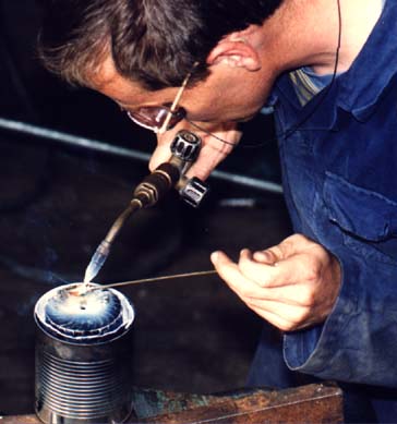 |
Fig. 4.11: Soldering a runner. |
Then on the actual soldering itself. First one could heat up the whole of the side disk for say 15 seconds, moving the flame around from above in large circles. I got the best results by working in 4 goes:
When satisfied, turn it around and solder the other side disk.
When soldering is finished, take it out of the container and let it cool down for a few minutes. Never pour water on very hot objects as it might affect the quality of the steel. Only once it has cooled down to less than say 200 °C, you might let it cool down faster by pouring water over it.
| Box 4.10: Strength problem.
The strength of the runner determines the maximum head (without blocking timber) the charger can stand without risking that blades will break out. Don't be fooled by how sturdy the runner looks and in fact is for single test forces. It is a fatigue strength problem: With every revolution, a blade experiences forces from the water when it rotates past the nozzle, and no forces when it is somewhere else (the forces when it is in the area where the water leaves the runner, are smaller and unimportant in this respect). Then after many hours of satisfactory functioning, the first blade might come out. This would make that the next blade is hit by twice as thick a slice of water from the nozzle, so not long after, this blade will break and so on. Only when a runner has survived 10 million revolutions (83 operating hours at 2000 RPM) at a certain head, it is safe to assume that this runner will last forever at that head (or rather: Until the blades have become noticeably thinner due to oxidation or the grinding action of silt in the water). The critical point in this is the joint of the blades with the alternator side disk at the outer radius. Here, stresses in the blade are highest so a crack is most likely to develop here. There is literature on this strength problem in crossflow turbines (e.g. VERHAART, 1983 and VAN DER VELDEN, 1985) and using Verhaart's method for calculating the strength of a firefly runner, the maximum head would be only 13 m (instead of the 15.6 m stated in par. 4.1). However, as far as I can see, those calculations are not directly applicable to the firefly design because:
So using strength calculations designed for standard crossflow runners and checked with experiments on these, gives little certainty about the maximum head for a firefly runner. Results with the first firefly prototype gives some information:
This is why I think that a reasonably well soldered firefly runner should be able to stand a maximum head of 15.6 m, so 20 % higher than the maximum head according to VERHAART's calculation. To find out more precisely what is the maximum head for a firefly runner, I want to test a perfectly soldered runner at very high head until it breaks. I can not afford to test it for many hours but there is no need for this: If I know that it survived for so many revolutions at a certain head, I can calculate back how much lower the head should be for it to last those 10 million revolutions (meaning: forever). This test should tell what the maximum head is for a perfectly soldered firefly runner, let's call this `100 % strength'. Probably this 100 % will end up somewhere between 20 and 30 m. Then one could rate runners according to the accuracy of building and the quality of soldering:
This quality rating system implicates that a runner with one or more blades missing is still usable, as long as no two subsequent blades in a row are missing. However, a runner with a blade missing can be a `normal' runner at best (it is quite unlikely that one will come across a `perfect' or `good' runner with just one blade missing: When operating at a head that was high enough to make one blade break out, the next blades in the row will soon follow. Please note that this quality rating system is based on an `educated guess'. The `perfect runner' is well defined and a maximum head test on another `perfect' runner will give about the same head: Results are replicable. Once inaccuracies and soldering errors come into play, it becomes very hard to predict strength. One runner rated as `poor' could in fact turn out to be stronger than a `normal' one in which inaccuracies and soldering errors cooperated to make two subsequent blades rather weak, resulting in the third, fourth etc. ones to break out soon after since these will get a progressively thicker slice of water to deal with. This also means that it makes little sense to test the maximum pressure of one or 2 `normal' runners: Results could vary so much that one should test 10 or more before one could draw conclusions about the strength of these runners. Normally, a safety factor is included in strength analyses. Here I didn't because:
So the maximum head of 15.6 m that was given in par. 4.1 is rather arbitrary. Probably it leaves a safety factor of about 2 when comparing it with the maximum head of a perfect runner, but one can only be sure after such a perfect runner has been pressure-tested. Then still the safety factor for lower quality runners will be much less. Probably only firefly runners that rate `good' or `perfect' will stand the maximum head of 15.6 m indefinitely. |